
Tech Talk by Korda Engineering
Sizing Technology Rooms
During the programming phase of any new construction or major renovation project, space allowances must be determined and accounted for the mechanical, electrical, plumbing and technology (MEPT) rooms. With increasing IT demands, sizing and location of the technology rooms is becoming more critical every day.
The following guidelines determined by BICSI are followed throughout the industry. BICSI is the worldwide association that establishes standards and best practices for the Information and Communications Technology (ICT) industry. These sizes are based upon providing two low-voltage jacks per 100 square feet of usable floor space throughout the building.
Table 1:Telecommunication Room (TR) Size Guidelines
|
Each building typically has one main telecommunications room (MTR) and as many additional telecommunications room (TRs) as necessary. As a rule of thumb for a typical office building, the MTR should be at least 8’x12′ and each TR should be at least 8’x10′. Providing these minimum dimensions is important to maintain the clearances necessary for servicing the front and back of each equipment rack. Exposed ceilings are preferred to permit maximum flexibility and accessibility, and a 10′ clear height is desirable.
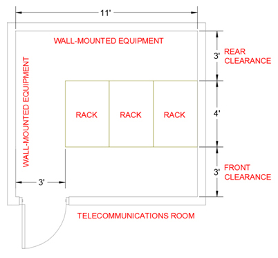
Figure 1: Telecommunications Room (TR) Layout
The number of devices being placed on the network is constantly increasing. Research estimates that more than 30 billion devices will be connected to the Internet of Everything by 2020. Using typical copper network architecture, this means that significant spare capacity needs to be provided as the size of the technology rooms will continue to grow.
Locating Technology Rooms
The data cable (e.g., Cat-6) from the TR to the work area outlet (i.e., the jack in the wall) shall not exceed 90m (295 ft). When accounting for pathway routes and vertical runs, vertical runs up and down walls and service loops, this distance on the drawings is actually much less than 295 feet. As a result, a good rule of thumb is that every point in the building should be within a 200 ft radius of a TR.
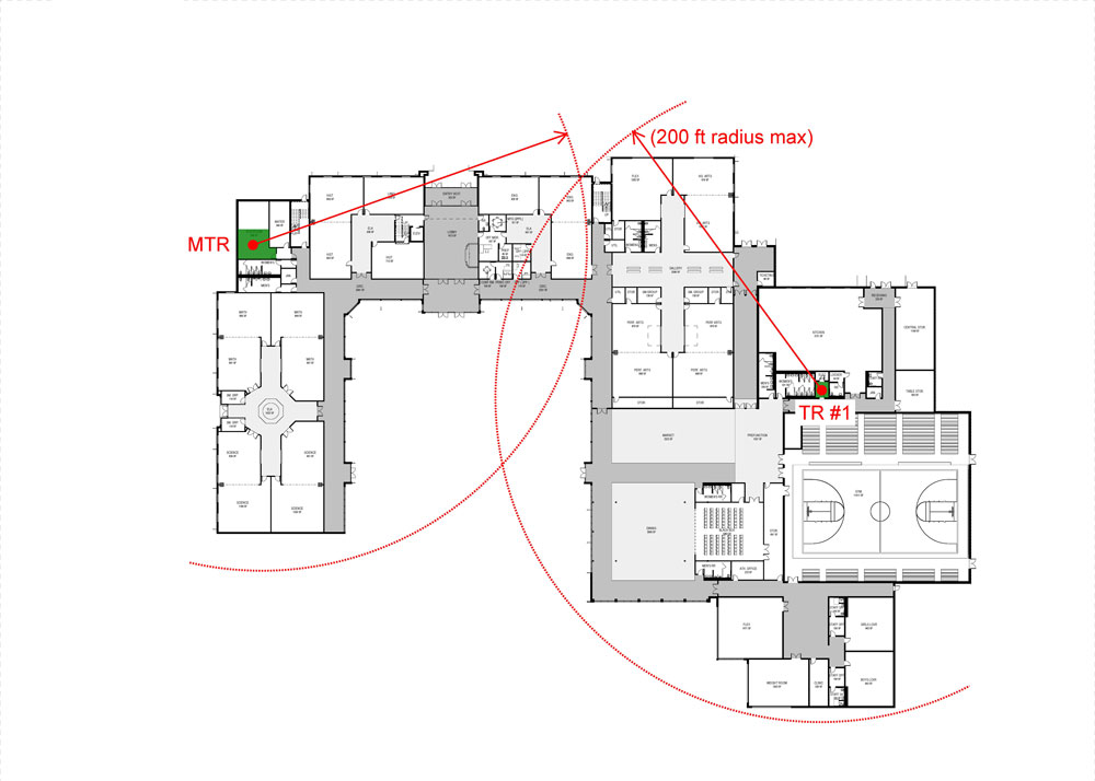
Figure 2: TR Serving Area Radius
Technology equipment and the cabling needed for it is rapidly changing. Providing Technology Rooms that are properly located and sized is very important to “future-proof” buildings for the next big thing. Considering Apple now has a watch, you never know what the next big thing will be.
|
|
||||||||||||||||||